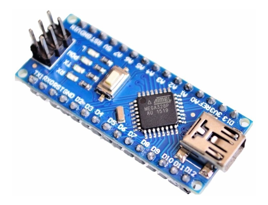

Arduino NANO BoardĪrduino NANO is the open-source microcontroller development board based on the ATMEGA328P microcontroller IC. So sit back, keep reading and enjoy learning. In this post (Arduino NANO for Beginners)I will discuss the overview of the Arduino NANO board, pinout of the Arduino NANO, specifications of the Arduino NANO, microcontroller IC on which Arduino NANO is based and finally the comparison of the Arduino UNO and MEGA board with the Arduino NANO board. For beginners it is just easier to use the markings on the board - the Arduino pin number - instead of bearing with the ports and their SFRs directly.Introduction to Arduino NANO for Beginners:
#ARDUINO NANO HOW TO#
Refer to the Documentation on Port Manipulation for learning how to do it yourself. Functions like pinMode(), digitalWrite() and digitalRead() all just manipulate the SFRs for the wanted port to set the respective pin. Arduino pin D8 is also named PB0, so PortB first pin. When you look at this pinout of the Arduino Nano, you see, that the Arduino pin D2 is also named PD2, which means PortD third pin (counting from zero up). These groups are called Ports, and are numbered with characters. For the digital output hardware the pins are sorted into groups of up to 8 pins. These are special pieces of memory, which are physically hardwired to the respective hardware in the microcontroller.
#ARDUINO NANO CODE#
Actually the code controls the hardware functions via Special Function Registers (SFR). The numbering in digital and analog pins is only an additional abstraction layer to hide the complexity from beginners. That means, that the code only knows of the function hardware and that it can be connected to their respective pins (whichever these pins are on the outside world). When I use analogRead(A1) I tell it to connect the second analog channel of the ADC to its respective pin and read an analog voltage through the ADC.

When I use pinMode(2, OUTPUT) I tell the microcontroller to connect the third digital output hardware to its respective physical pin. The code has to decide, what hardware gets to be connected to the respective pins. Most pins of a microcontroller are multi purpose. But they also each have digital input and output hardware, just like any other digital pin. For example: The analog pins can be used by the ADC (Analog to Digital Converter) to measure an analog voltage. In case you want to go deeper into the rabbit hole:Īctually the microcontroller has different hardware for different functions incorporated. As reference the numbers are also printed on the Arduino board itself. The Arduino way of counting the digital and analog pins just hides away complexity for the beginner. So internally we use a different counting system based on the pin function. But the internal code doesn't know, where the physical pins are located and the actual location can also depend on the packaging. TL DR: For building the circuit we must refer to pin positions (like where is Vcc, where is ground) to connect the chip/microcontroller correctly. For the code its just the third digital output hardware and so on. Where that pin is physically located on the board isn't interesting for the code, nore does the code know the actual location. So D2 means the third digital pin inside the Arduino framework. Those are the numbers, that are normally written only the Arduino board. So for the convenience of beginners (which are targeted by the Arduino framework) the digital and analog pins are just numbered. On an Arduino you have mainly digital and analog pins, which can be controlled. So this counting only makes sense in the context of placing this specific package of the chip into a circuit (like where is Vcc, where ground and where do I need to connect to that specific digital pin), but makes no sense to use for the code inside the controller.įor referring to pins from inside the controller (aka in the code) we use the function of the pins. Each package has a different pin order and form factor. Also the microcontroller on the inside of its package doesn't know in which package it got stuck by the manufacturer. Those pins cannot be referenced by the code (wouldn't make much sense). This also includes special pins like Vcc, GND and Reset. The first way is only for referring to specific pin positions from the outside, for example when you are building the actual circuit. Referring to the pins by their function.Counting the physical pins in the order as they appear on the chosen package of the chip.Every chip datasheet (and also the Arduino boards) uses 2 different ways to refer to the pins:


 0 kommentar(er)
